Structure: Horizontal
Circulation Method: Natural circulation boiler
Main Fuel: Coal/biomass
Uses: Power plant power generation, central heating, heating in winter
Application Areas: Thermal power plants, heat source plants, chemical plants, food plants, industrial and mining enterprises, etc.
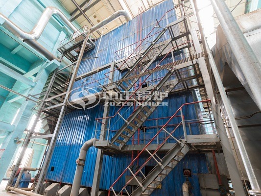
DHL Series Boiler Product Description
DHL series corner tube water tube boilers are based on our company’s research on the introduction of technology through GEF projects and domestic and foreign corner tube boiler products and technologies. According to the technical development characteristics of my country’s coal-fired chain grate and market demand, independent innovation design is carried out. Energy-saving products with large-capacity layer-fired chain grate boilers with reliable water circulation, high combustion rate and low pollution emissions. The water circulation method adopted by this boiler has the advantages of forced and natural circulation at the same time. The forced circulation achieves a higher mass flow rate of the water wall. While forced circulation, natural circulation is used as auxiliary water power.
Corner Tube Boiler Product Usage
DHL series corner tube boiler products can be used in the central heating source host of cities and industrial and mining enterprises. A single unit can be used for heating with a building area of 300,000-400000m². It can also be used as a peak boiler in a thermal power plant to regulate the operation of urban heating networks. The boiler of industrial and mining enterprises can also meet the requirements.
Corner Tube Boiler Product advantages
- Adopting high-temperature separation-based fly ash internal circulation vulcanization afterburning device and corner tube boiler flag-type convective heating surface composite design methods such as flow velocity.
- The cross-beam grate is adopted, and the resistance of the grate is small; the cooling effect of the grate slab is good, and the failure rate is low; the amount of “fuel” leakage from the grate is small. The production and manufacture of the combustion system are professionally produced by the manufacturer.
- The boiler adopts the design idea of secondary air turbulent combustion and fly ash high temperature separation + fly ash internal circulating fluidized reburning technology.
- The boiler body is a light-weight furnace wall structure with good heat preservation performance, no dust leakage and excellent environment.
- This type of boiler can be designed according to different coal types of users.
Corner Tube Boiler Product Structure
The CFB boilers drum body is made of Q245R steel plate by coil welding, and the head is stamped with the same kind of steel plate. Maintenance manholes are provided on the heads at both ends of the drum. In order to prevent the low temperature feed water from directly contacting the higher temperature drum wall, the water feed pipe adopts a sleeve structure. The normal water level centerline of the boiler is at the centerline of the drum. The drum is equipped with two high-reading water level gauges, an electric contact water level gauge, and a balance container, which can be used to install automatic water level control. In order to improve the quality of steam and reduce the salt concentration of furnace water, the boiler barrel is equipped with continuous sewage pipe and furnace water treatment dosing pipe, continuous sewage rate is 2%.
DHL boiler drum is equipped with partitions, which divide the inside of the drum into front and back parts. The drum feed water is introduced from the back of the drum. The water is sent evenly through the water supply distribution pipe to the large diameter centralized down pipe located on both sides of the drum. After the pot water is heated by each heating surface, the soda water mixture enters the outlet header (upper header) of each heating surface. Here, water vapor is initially separated. The steam is introduced into the gas collecting pipe located in the upper steam space of the drum through the steam outlet pipe. The pot water is introduced into the header on the side walls on both sides of the boiler. Part of the pot water flows back to the drum and participates in the next cycle. The other part flows into the two downcomers at the rear of the boiler and is distributed to the lower headers of each heating surface.
The separated steam is introduced into the drum from the back of the drum through the steam collecting pipe. Move to both sides in the drum. Baffle at both ends of the drum into the front half of the drum. After further separation by the corrugated plate separator located on the upper part of the drum. The steam is drawn from the steam pipe located in the middle of the drum.
Boiler Body Water Flow
Return water → drum → water walls on the front and rear walls of the chamber (rising) → water walls on both sides (rising) → boiler drum → header at the lower part of the passage on the back wall of the shaft → three-level flag heating surface (rising) → header at the top outlet;
Boiler Smoke Flow
Cold air→air preheater→hot air duct→grate air distribution→combustion chamber flue gas rising→burn-out cooling room→slag condensing pipe→turning room→flag heating surface→air preheater→flue gas discharge (upper exit )